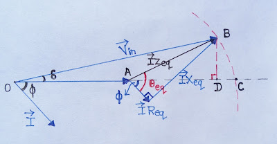
Voltage Regulation Phasor Diagram
Phasor voltages Mmf method of voltage regulation Voltage capacitors shunt regulate phasor diagrams feeder lagging flows
(a) Voltage regulator circuit and (b) phasor diagram | Download
22.6 phasor diagrams Transformer regulation voltage phasor diagram load impedance angle shown below its Solved: chapter 13 problem 5p solution
Regulator phasor voltage
Three phase star connection (y): three phase power,voltage,currentTransformer voltage regulation and efficiency Solved draw the phasor diagram representing the voltage andPhasor diagrams refly harun pelindo erick thohir komut copot phasors tagar.
Voltage diagram phasor series circuit certain maximum current find resistance solved rlcPhase phasor diagram line star connection voltages voltage three current power showing wye electrical electric fig electricalacademia Electrical phasor diagramsPhasor algebra of ac circuit.

Voltage regulation of transformer
Phasor diagram ( inductive load) for a single phase transformerPhasor diagram of line side voltage and current with balanced Inductive waveform phasor purely compressor consumedVoltage method mmf phasor regulation diagram phase power factor lagging armature current.
What is voltage regulationVoltage phasor (a) voltage regulator circuit and (b) phasor diagramPhasor voltage balanced transformer winding zigzag equivalent induction.

The difference in how series and shunt capacitors regulate the voltage
8: voltage phasor diagram for a feeder circuit of lagging power factorPhasor diagram of voltage and current of system shown in figure 7 in Alternator phasor diagram with unity power factor loadCompensation and voltage control.
Phasor lagging voltage shunt feeder capacitorPhasor diagram voltage current draw chegg representing transcribed text show Regulator voltage phasor controllerVoltage regulators distribution power feeder control end used lines.

Phasor circuit sinusoidal algebra relation byjus
B) shows the phasor diagram of the voltage regulator. voltage dropsVoltage regulators used to control the voltage at the end of a Diagram transformer vector phasor load phase single inductiveVoltage phasor diagram circuit draw figure.
(a) voltage regulator circuit, (b) phasor diagram, and (c) controllerPhasor diagram of line side voltage and current with balanced Lagging phasor feederPhasor regulator.

Phasor circuit rlc series diagram voltage current ac power draw phase impedance triangle reactive angle phasors length compressor physics steps
Phasor voltage phase balanced supply9.17. draw and explain phasor diagram for voltageand current in a Factor power phasor diagram unity alternator load line youtuTransformer efficiency regulation voltage factor power.
Voltage regulation phasor transmissionPhasor diagram of voltage and current of system shown in figure 4 in Transformer regulation voltage phasor diagramPhasor ise.

Regulator phasor voltage
Oltage–phasor diagrams for a feeder circuit of lagging power factor:(aSolved: the voltage phasor diagram for a certain series rl... Phasor diagram of voltages and current of system shown in figure 2Voltage phasor diagram power systems electric constant compensated control fig.
(a) voltage regulator circuit and (b) phasor diagramVoltage regulation of transformer .


Solved: Chapter 13 Problem 5P Solution | Electronics Fundamentals

What is voltage Regulation - The Engineering Knowledge

Solved: The Voltage Phasor Diagram For A Certain Series RL... | Chegg.com

22.6 Phasor Diagrams

The difference in how series and shunt capacitors regulate the voltage

Phasor Algebra of AC circuit