Servo Valve Circuit Diagram
A). principal schematic of servo control valve. Servo motor embedded Servo-valve module:
Electronics schematic diagram for the servo-control circuit. All
Valve servo circuit electrical hydraulic hydrostatic transmissions Schematic servo Servo voltage references position switch circuit schematic
Fun with servos – circuit crush
Servo circuit control simple driver motor diagram build schematic do circuits arduino schema ac motors board diy electronic signal circuitoElectronics schematic diagram for the servo-control circuit. all Servos fun servo arduinoValve servo equivalent.
Servo equivalent electricalServo amplifiers What is a servo valve?Servo amplifiers.

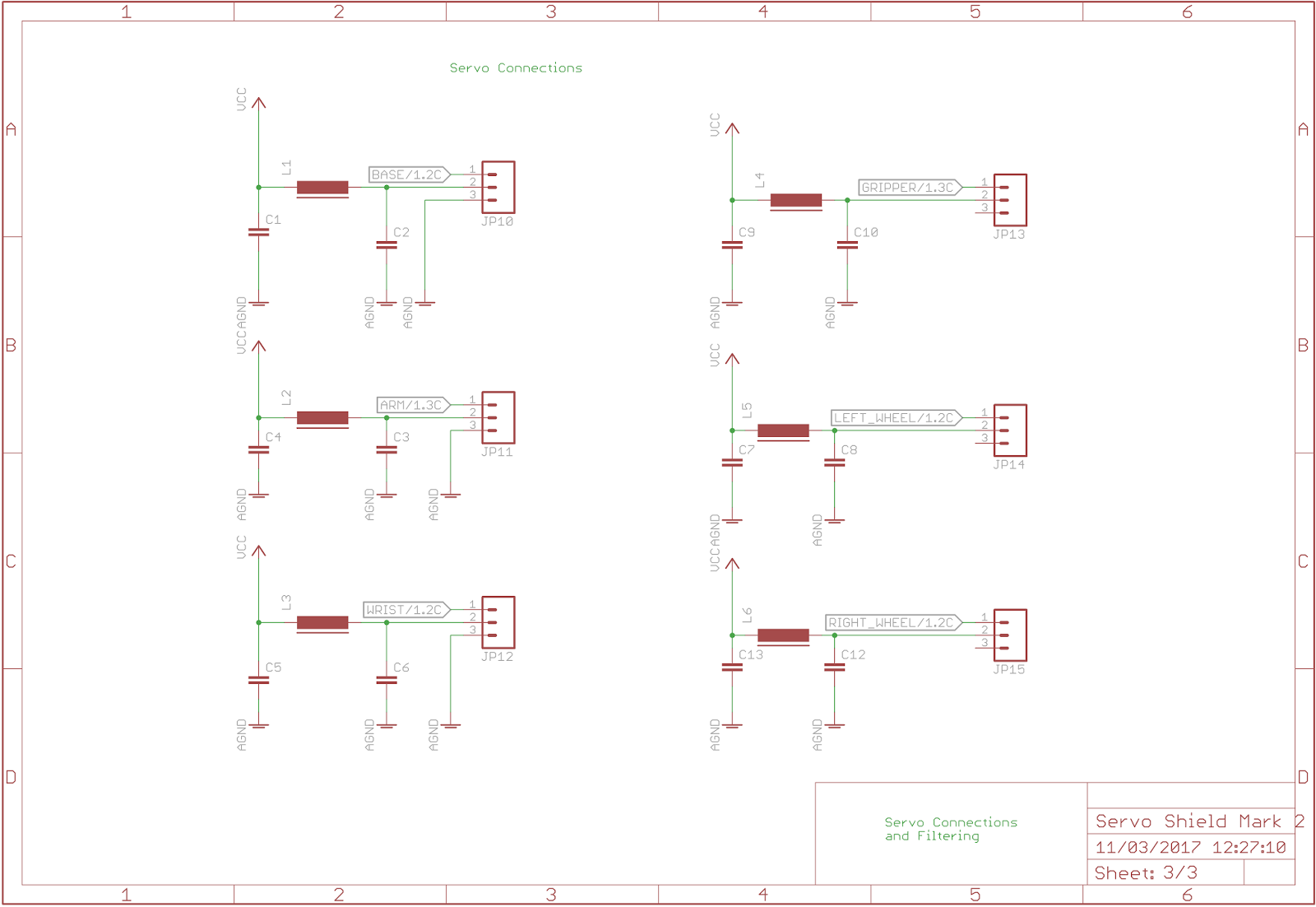
Servo answer filtering connections diagram
The answer is 42!!: march 2017Dc servo & stepper motor Servo motor circuit 555 control diagram ic controller timer using diagramsServo controlling circuit.
Hydraulic electro servo mathematical compositionDiagram of the test set up. when the servo valve is used to control the Servo operational pneumatic oscillator amplifiers cdm lpfServo-valve module.
Electronics schematic diagram for the servo-control circuit. all
-a) servo-valve schematic. b) servo-valve electrical equivalentCircuits servo 10v schema servos controlling volt Circuit hydraulic valve servo diagram electro drive seekic supply powerServomechanism (tracking mechanism).
Schematic representation of the wiring diagram depicting the control ofComposition of electro-hydraulic servo control system 2 mathematical Circuit servo control servos schematicServo stepper.

Servo instrumentation automationforum
How do you build a simple circuit to control a servo?How to use servos in your electronics projects Servo valve electrical circuitServo hydraulic system electro valves valve two schematic speed test fig motor troubleshooting frequency response applied vibration machine high shows.
-a) servo-valve schematic. b) servo-valve electrical equivalentServo motor wiring diagram database Servo valve module schematicServo representation depicting.

Servo motor control using 555 timer ic
Servo amplifiers troubleshooting valves schematic hydraulicA schematic diagram of an electro-pneumatic servo-drive with a fuzzy Servo motor wiring httpsakLab 21: servo motor control.
Electro-hydraulic servo valve drive circuit diagramServo valve schematic module circuit amplifier power motor amp gives example Circuit designPneumatic servo schematic electro fuzzy logic.


Electronics schematic diagram for the servo-control circuit. All

Electronics schematic diagram for the servo-control circuit. All

What is a servo valve? | Instrumentation and Control Engineering

-a) Servo-valve schematic. b) Servo-valve electrical equivalent

a). Principal schematic of servo control valve. | Download Scientific

Lab 21: Servo motor control - Embedded Lab

The Answer is 42!!: March 2017